
10th July 2020
In a previous post, we talked getting the most out of working with Curved Axis on architectural visualisation projects. The main purpose of that post was to give people a better understanding of how we work and to highlight the importance of communication throughout the visualisation process. In today's post, we are going dig a bit deeper and take an in-depth look at 3D rendering itself, breaking down the various stages.
According to Wikipedia, it is:
the 3D computer graphics process of converting 3D models into 2D images on a computer
While this is technically accurate, the term is used across many industries to describe the wider visualisation process. For architectural visualisation, this process starts with CAD plans and ends with the delivery of production quality CGIs. Much like in a 3D animated movie, it starts with concept sketches and finishes with the final edit of the film.
Whichever industry we look into, 3D rendering breaks down into the following stages:
These steps are often treated as a linear process, but we believe this stifles the iterative creative process. Having to completely finalise a lighting rig before starting texturing is counterproductive and limits an artists' freedom.
These steps are the building blocks for all our visualisation work. From interior design rendering and architectural visualisation to interactive 3D virtual tours. Architectural animation differs slightly, with an additional animation step.
Let's take a look at what each stage involves.
This is the process of creating three-dimensional forms that we call models. These polygonal models are mathematical representations of objects made up of vertices, edges, and faces.
These components are moved around and manipulated into the desired shape. Think of this process as the digital equivalent of moulding clay or building the structure of a real-world physical model.
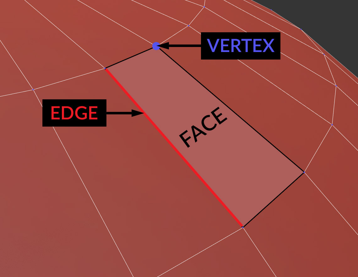
An illustration showing the difference between vertices, edges and faces.
It is good practice to create models that are predominantly made up of quads (faces with four edges) and capture detail with as few polygons as possible. The number of polygons that a model has is referred to as its polygon count, and models with higher polygon counts take longer to load.
The polygon count and load time of a model is far more important in applications where 3D models are loaded at runtime, such as video games. In architectural visualisation is it not as much of a consideration, as the final output is the rendered image and not the 3D model, therefore the visual fidelity of a 3D model takes priority over its optimisation.
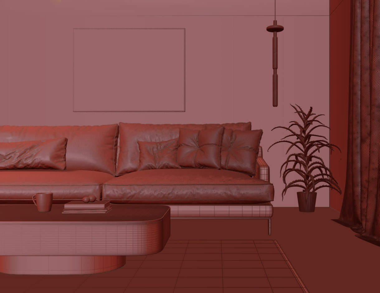
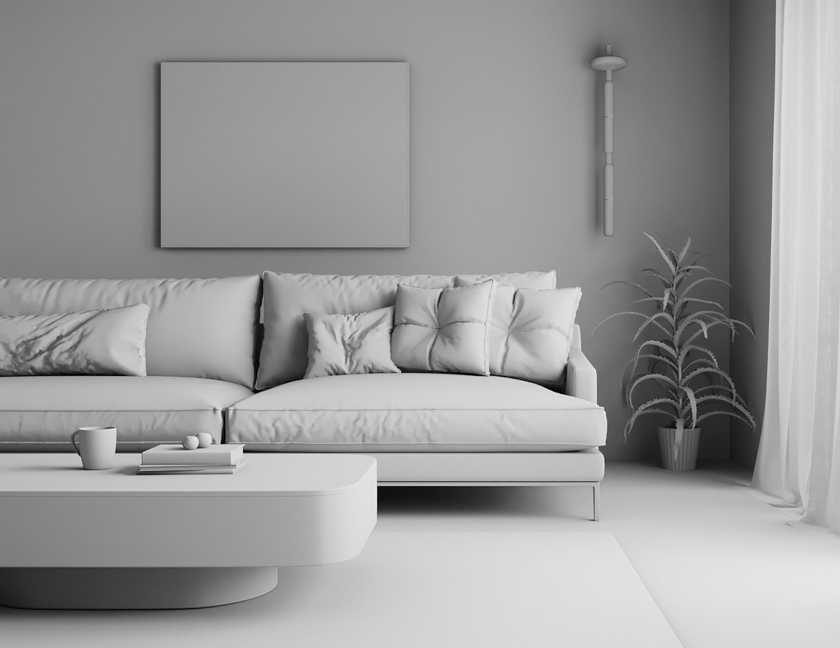
In architectural visualisation, the most common goal when modelling is to create an accurate depiction of an object that exists (or will exist) in real life e.g. buildings, trees, roads etc. As a result, 2D CAD plans and photographic references are vital to ensure that models are built correctly and are photorealistic.
A hugely important and often overlooked step in the visualisation process is lighting. Like in the real world, without light, we wouldn't be able to perceive the objects or materials in a 3D scene. HDRI (high-dynamic-range imaging) skies help achieve realistic exterior lighting, much like IES (Illuminating Engineering Society) profile lights add realism to interiors.
HDRIs are images that contain much more colour information than a standard photo. They are created by merging together multiple exposures into a 32-bit image format. This additional colour information, allows artists to use HDRIs to light their scenes. 360° HDRIs are great for capturing real-world lighting environments and recreating them in 3D, they provide accurate reflections as well as the lighting information.
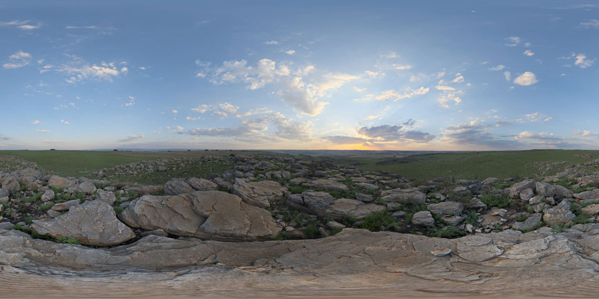
A low-resolution JPG version of a HDRI from HDRI Haven - Kloppenheim 06
An IES file (or profile) describes the distribution of light from a light source using real-world data from the manufacturer. It is essentially a digital profile of a real-world light. As such, IES profiles allow artists to accurately recreate lights from the real-world and provide an added level of realism to their visualisations.

A rendered preview of an IES profile
These formats and techniques allow artists to achieve photorealistic results with relative ease, but lighting is so much more than just matching reality. In 3D rendering, the possibilities are limitless and lighting is a powerful artistic tool that allows us to convey a story. Lighting sets the mood, draws the viewers focus and can make the audience fall in love with an image.

Without materials and textures, all our CGIs would be clay renders. This part of the process involves assigning materials to our models, these materials range from brick or suede to natural surfaces such as a leaf from a tree.
A typical PBR (physically-based rendering) material in an architectural visualisation workflow will consist of three textures (or maps) that define its properties. A diffuse map, which is the colour of the material. A glossiness map, which controls how sharp or diffused the reflections of the material are. And a bump map, which controls the relief or "bumps" on the surface of the material. There are other types of maps but these three alone allow you to create realistic representations of most of the materials you interact with on a daily basis.
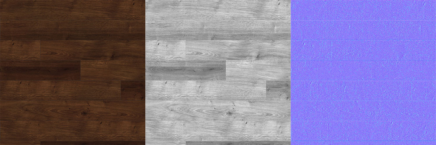
Diffuse, gloss and normal maps for a dark wooden floor material.
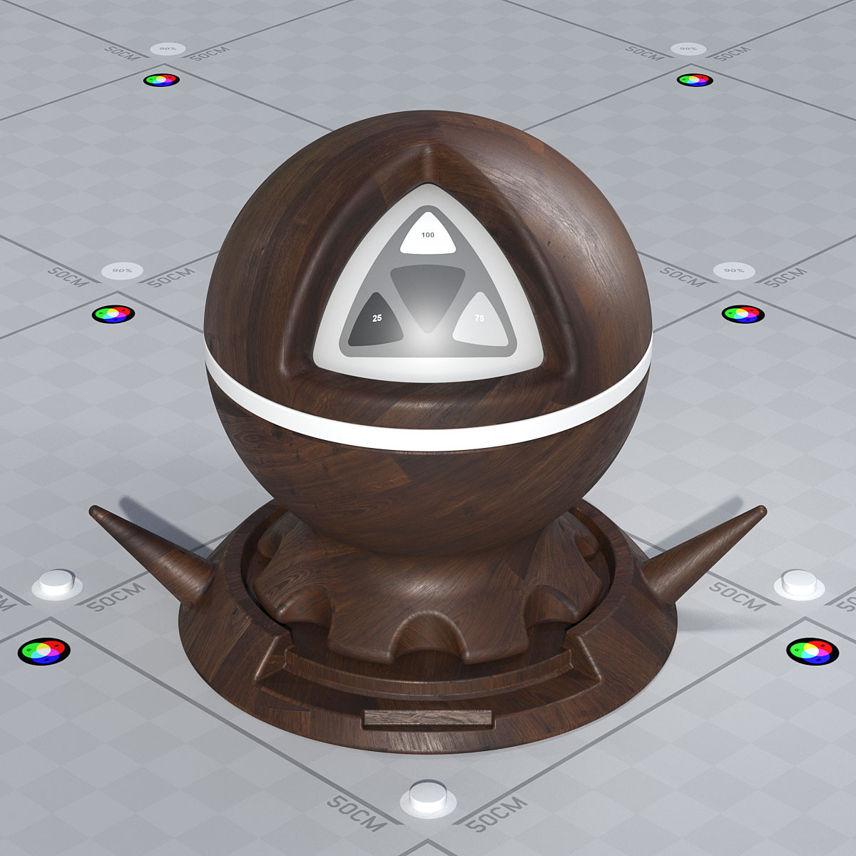
A rendered preview of the dark wooden floor material.
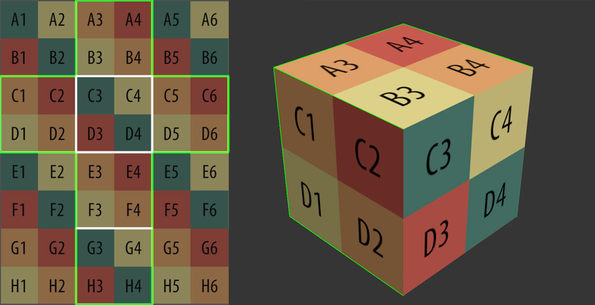
2D Textures are applied to 3D geometry using a process known as UV mapping. The UVs of a model determine exactly how a texture should be applied - the scale, rotation, proportion, position, etc.
The best way to understand UVs is to consider them as the net of a 3D model. Think about if you were to unfold a cube, you would end with six connected 2D squares. This concept of unfolding (or unwrapping) is the same in 3D modelling, where artists rely on tools provided in 3D software packages to unwrap their models.
Another important characteristic of a PBR material is its reflectivity. A common mistake is to confuse materials with diffused reflections as having a lower reflective value, but this is not physically correct. The reflective value of all dielectric (non-metal) materials should be set to pure white or 1.0. Reflective qualities of a material are more accurately controlled using the glossiness map and Fresnel IOR (index of refraction).
Fresnel refers to the observation that the amount of light reflected from a surface is based on the angle it is viewed from. Try it yourself - if you observe materials from as close to the angle of the surface as possible, you will notice it has stronger and sharper reflections. The Fresnel IOR of a material controls this effect, higher values give materials stronger reflections when viewed from a perpendicular angle. As a result in 3D, metal materials have an IOR value of between 50-999 and dielectric materials around 1.52.
This part of the process is only relevant to animations and involves adding motion to a 3D scene. Depending on the type of project. This could be, the motion of a camera in an architectural fly-through. Or elements that bring a scene to life in an animation, such as, people walking, trees swaying in the wind or clouds moving in the sky.
Adding realistic animation to a large scene can be a sizable task. This combined with long render times of animations make cinemagraphs an attractive solution. A cinemagraph is a predominantly still image that has an element with a subtle looped motion. It is a great way to add interest to a CGI without dramatically increasing the render time. We have some examples of cinemagraphs in our portfolio. One is an interior CGI with a moving curtain and another, a fire flickering in an exterior CGI illuminating the night.
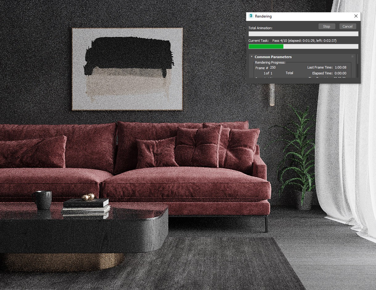
Once the 3D scene is complete it is rendered out as a 2D image (or series of images). This is the part of the process the description at the start of the article is referring to - "the 3D computer graphics process of converting 3D models into 2D images on a computer". The computer calculates light bouncing through the scene and produces the final rendered output.
It is worth noting that rendering is computationally intensive. Depending on the task, it can take anywhere from a fraction of a second to multiple days. The duration of a render is dependant on many factors, including:
Consider a render with the resolution of 2000x1000 pixels (2k). If we double this to 4000x2000 pixels (4k) we are quadrupling the area that needs to be rendered. This is because both the horizontal and vertical axis double in size. Using the same logic, we can calculate that an 8k image will take 16 times longer to render than the same scene at 2k. Similarly, render times on an animation are much higher than those of a still CGI. This is due to the fact that 25 frames are rendered out for each second of animation to create the effect of smooth motion. A short 8 second rendered animation will consist of 200 individually rendered frames!
It is important to pay attention to a render's resolution, particularly for images that will be displayed on large formats such as billboards and hoardings. PPI (pixels per inch) is a unit that measures the number of pixels over a fixed distance (an inch) and as such it is useful for ensuring that the sharpness of a render is maintained across different sized outputs. DPI (dots per inch) is the equivalent of PPI for physical printed media, many people use these two terms interchangeably.
It is difficult to give a rule of thumb when it comes to pixel density, as it is largely dependant on the format and the distance of the viewer from the image. The further away a format is viewed from the lower the PPI can be whilst still retaining the quality.
Here are some examples of popular devices are their typical PPI:
The standard resolution of our CGIs is 4,000 pixels along the longest edge, this is more than enough for most applications. For reference, it is larger than 4K ultra high-definition video and is approximately the same resolution as photos taken on the latest smartphone cameras. In terms of print, a render with the resolution of 4,000 x 3000 pixels could be printed at 677 x 508 mm (larger than A2) at 150 DPI.
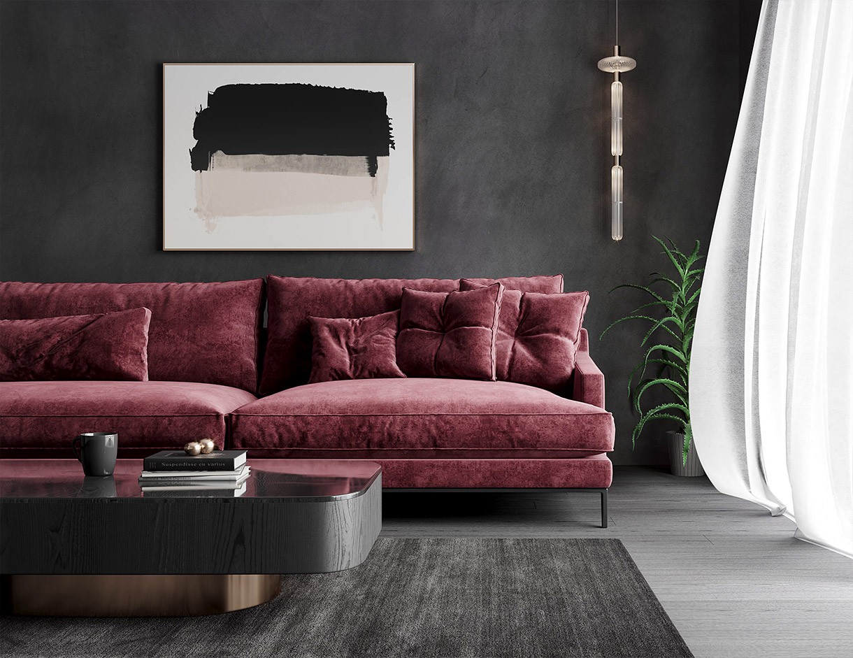
Once the raw renders have been saved out, they are taken into either Photoshop (still CGIs) or After Effects (animations) for some final polish. Post-production allows an artist to refine raw renders. They do this by fine-tuning the colours, contrast, and exposure settings. Before settling on a final version that delivers the intended message and emotion. This is similar to the final step taken by a photographer before delivering the edited images.
So, now that we have covered the process. Let's take a look at how 3D rendering has become such a large part of so many different industries. The reason for most is quite simple. It allows you to create anything that you can imagine. It removes physical limitations, it is economical, versatile and does not require large amounts of resources. In architectural visualisation, this means being able to drop out of the sky into a development that has not been built yet. To adapt interior design schemes in real-time virtual reality. Or to interact with a building design during a client meeting using augmented reality. It opens up so many possibilities!
We hope this helped develop a better understanding of what goes on behind the scenes here at Curved Axis. Although the focus here was on interior design rendering and architectural visualisation. These steps are present in every use of 3D rendering. From 3D animation and Hollywood VFX to video games.
Let us know what you think! Would you like to see more content like this? Or have you got a question for us? Either way, we look forward to hearing your thoughts and continuing the discussion.
Alternatively, if you want to talk about career opportunities, discuss an upcoming project, or just say hi, we would love to hear from you too!